Learn Line Protection Panel Schematics
"softddl.org"
11-11-2022, 10:48
-
Share on social networks:
-
Download for free: Learn Line
-

Instructors: Elite Engineering
18 sections • 18 lectures • 1h 58m
Video: MP4 1280x720 44 KHz | English + Sub
Updated 8/2022 | Size: 684 MB

Instructors: Elite Engineering
18 sections • 18 lectures • 1h 58m
Video: MP4 1280x720 44 KHz | English + Sub
Updated 8/2022 | Size: 684 MB
Electrical Power System Protection
What you'll learn
Line Protection Panel Schematics
AC,DC Loop
Supply Changeover circuit
CT & VT circuit
Trip Circuit, Close Block, Lockout circuit
Requirements
Basics of electrical
Description
Dear All,
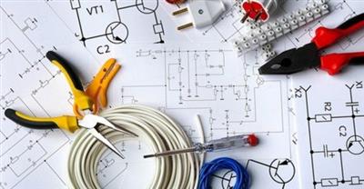
Designing, installing, and troubleshooting of electrical systems requires the use of various drawings to give engineers, installers, and technicians a visual representation of the systems they work with.
Electrical equipment and circuitry is often expressed as symbols and lines that represent the various components and connections within a system. The level of complexity within an electrical drawing will vary depending on the intended purpose and personnel working with the drawing.
Design engineers and technicians use schematics to build and troubleshoot complex circuits, while plant operators use single-line and riser diagrams to facilitate switching operations within their distribution system. Knowing how to read and interpret various types of electrical drawings are an essential skill that all electrical workers must posses to effectively carry out their tasks.
The symbols and lines within an electrical drawing speak a language that everyone involved must understand in order to design, build, and troubleshoot electrical systems. In this article, we will briefly describe several types of common electrical diagrams encountered in the field and explain their purpose
Designing, installing, and troubleshooting of electrical systems requires the use of various drawings to give engineers, installers, and technicians a visual representation of the systems they work with.
Electrical equipment and circuitry is often expressed as symbols and lines that represent the various components and connections within a system. The level of complexity within an electrical drawing will vary depending on the intended purpose and personnel working with the drawing.
Design engineers and technicians use schematics to build and troubleshoot complex circuits, while plant operators use single-line and riser diagrams to facilitate switching operations within their distribution system. Knowing how to read and interpret various types of electrical drawings are an essential skill that all electrical workers must posses to effectively carry out their tasks.
The symbols and lines within an electrical drawing speak a language that everyone involved must understand in order to design, build, and troubleshoot electrical systems. In this article, we will briefly describe several types of common electrical diagrams encountered in the field and explain their purpose.
Best Regards
Who this course is for:students, technicians, engineers
Homepage
https://www.udemy.com/course/learn-line-protection-panel-schematics/Links are Interchangeable - No Password - Single Extraction
The minimum comment length is 50 characters. comments are moderated


